A multiplexer is a multiple port frequency distribution circuit, usually employed in a communication system to split input signals from a common port into several channels operating at different frequencies. It can also be used to combine several channels into a single composite signal for transmission through a common antenna. Multiplexers have many applications for instance satellite payloads and wireless communication systems.
The common approach to the synthesis of a multiplexer involves designing each channel filter individually and combining with a frequency distribution network formed of circulators, hybrid couplers, or manifolds. In the research here, multiplexer structures are based only on resonators This multiplexer structure eliminates the need for separate transmission-line based frequency distribution networks leading to a reduction in the overall component size and volume. The synthesis of this all-resonator multiplexer is based on optimisation of coupling matrices. Various topologies can be explored by simply adding coupling coefficients into the matrix during the synthesis and we have investigated a number of different structures. This extra freedom offers new possibilities in selecting achievable topologies, such as the four-channel multiplexer structure shown in figure 1.
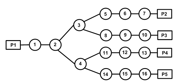
Figure 1: a four-channel multiplexer structure. It is based on 16 coupled resonators.
For a multiplexer with multiple outputs, the topology shown in figure 1 can be expanded and employed to divide the input signal into many sub-bands. In this case, none of the resonators has more than three connections, regardless of the number of outputs. This reduces the difficulty of physical implementation.
The sixteenth-order four-channel multiplexer shown in figure 1 has been demonstrated at X-band using waveguide technology. The multiplexer is made from aluminium and is shown in Figure 2. This multiplexer is based on 16 TE101 cavities that are coupled by inductive irises. These resonators are folded to offer a compact structure.
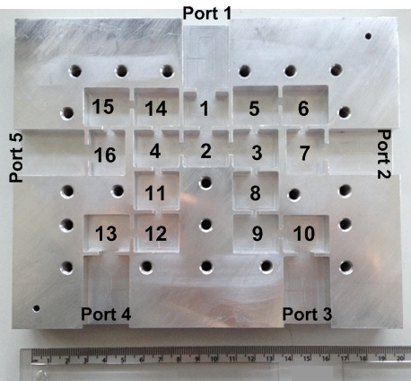 Figure 2: photograph of the sixteenth-order X-band four channel multiplier with the top cover removed.
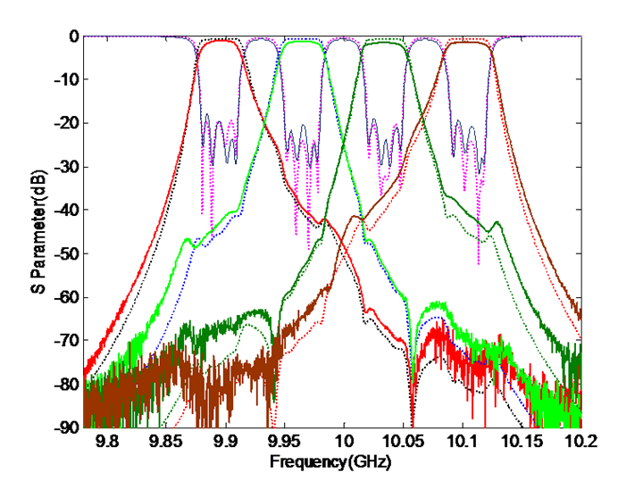 Figure 3: measurement (solid lines) and simulation (dashed lines) results of the four-channel multiplexer.
The measurement results are depicted in figure 3. Excellent agreement has been achieved between simulation and measurement.