Micromachining technology has been employed by our research group to demonstrate waveguide filters operating at W-band (75-110 GHz), WR-3 band (220-325 GHz) and WR-1.5 band (500-750 GHz). Here the WR-1.5 filter will be discussed in detail, not only to describe the filter as an example, but also to elaborate on the micromachining process.
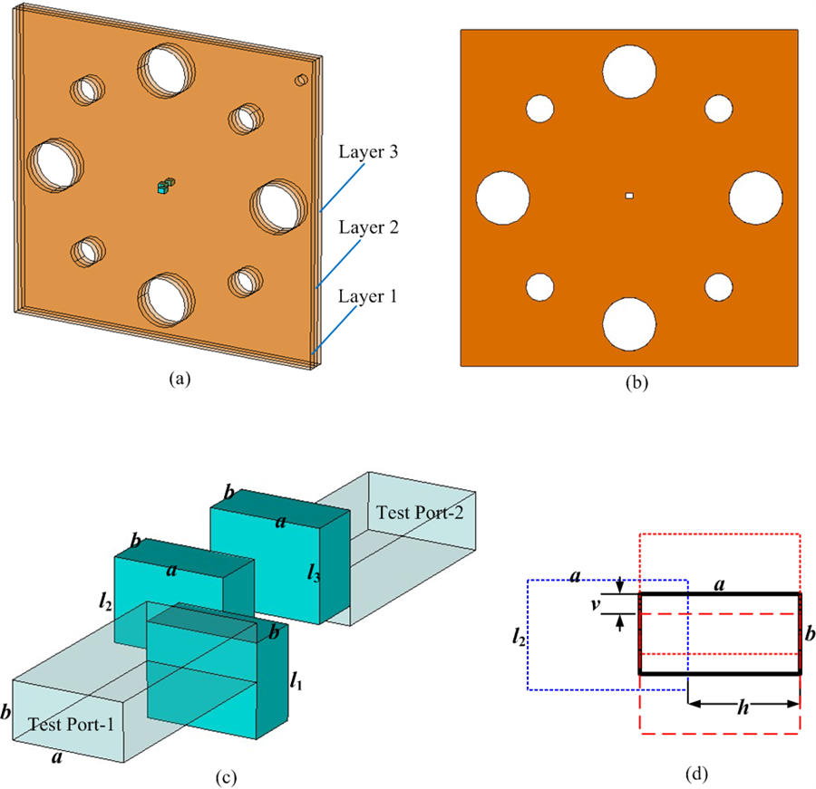 Figure 1: a WR-1.5 band filter formed of three SU8 layers with a same thickness. (a) Illustration of the filter. The standard UG-387 waveguide flange dowel pins holes and screws holes are shown. (b) Front view of one SU8 layer. (c) Diagram of the filter structure, which is the functional blue part also shown in (a). (d) A schematic front-view diagram of the filter structure. The first and third resonators are represented using red rectangles, whereas the blue rectangle represents the second resonator; the offset determines the filter properties.
As shown in figure 1, the filter is composed of three silver-coated SU8 layers, each of the same nominal thickness of 191 µm. Rather than placing the resonators in alignment and controlling the couplings through irises (as in a standard filter), this WR-1.5 filter shifts the relative positions of resonators to achieve the desired specified external and internal coupling coefficients and therefore the desired frequency response. This is shown in figure 1(c)-(d). This novel structure is ideally suitable for the layered SU8 micromachining process as it avoids irises features within a layer, and is thereby more robust for fabrication. It also has a very accurate flange for connecting to the measurement equipment. Figure 2 shows a photograph of several silver-coated SU8 layers before they are put together into the final filter.
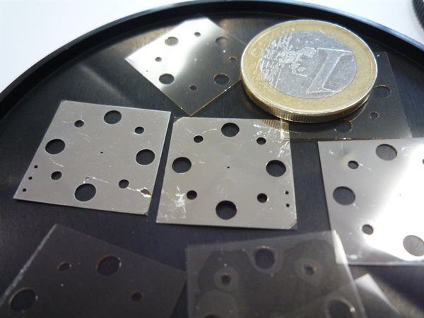 Figure 2: photograph of a few silver-coated and uncoated SU8 layers.
These SU8 layers are delicate due to their small thickness, and carefully mounted onto a separate metal straight though waveguide section and then inserted between the two ports of a network analyser to perform the measurement as shown in figure 3 (a).
Measurements of the filter were performed using an Agilent N5247A Vector Network Analyzer (VNA) with a pair of VDI (Virginia Diodes Inc.) extension modules. During the measurement the SU8 filter and the waveguide section were placed in the middle of two standard WR-1.5 waveguide flanges (i.e. UG-387), as shown in figure 3 (b). The four alignment pins of the waveguide flanges addressed both the accuracy to which the three SU8 layers were aligned and the accuracy to which the micromachined filter was aligned to flanges of network analyser.
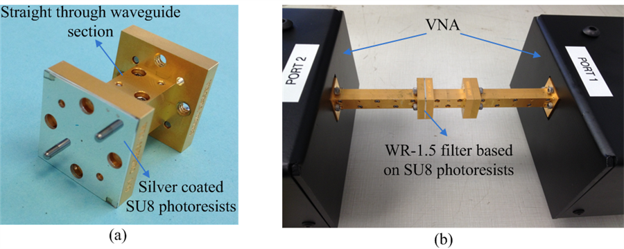 Figure 3: (a) SU8 shims mounted to a 1-in long straight through waveguide section. This prevents the SU8 shims from bending or wrapping. (b) Test setup for the micromachined SU8 waveguide filter.
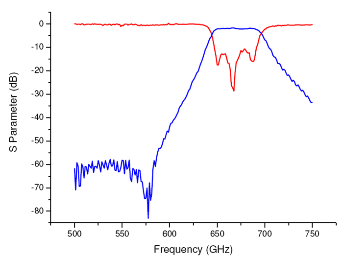 Figure 4: measurement results of the WR1.5 SU8 filter.
The measurement results of the SU8 filter together are shown in figure 4 which exhibits a 3 dB bandwidth of 53.7 GHz at a centre frequency of 671 GHz. The median passband insertion loss is measured to be 0.65 dB, which is close to the theoretical value of 0.28 dB obtained from a simulation using the conductivity of silver The measured return loss is better than 11 dB across the whole passband. These are excellent results and this filter is one of a very few demonstrated at this frequency in the world.