Amplifiers are employed in almost all aspects of microwave engineering for communications and radar systems. The amplifier is ordinarily preceded by filtering to select desired bands of frequencies and reject others for channel selection and compliance. Combining the amplifier and filter in a compact manner can improve performance, through removing intermediate impedance matching, but also in terms of component size and weight. High Q-factor waveguide based components are of interest where the lowest loss is required; they are used throughout the spectrum but are particularly employed in submillimetre wave or terahertz applications. As active components become more commonplace at hundreds of GHz, where planar circuit losses are significant, the technology of choice for interconnects and filters are high-Q waveguides. Combining the filter efficiently with an amplifier is a project developing in the EDT group, here we described a 10 GHz prototype, but work is also with amplifiers at 300 GHz.
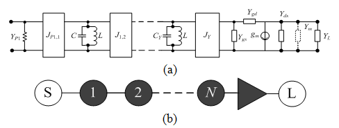 Fig. 1: topology and equivalent lumped circuit for coupled resonators filter-amplifier circuit. (a) Lumped circuit model. (b) Schematic representation of the circuit.
Figure 1(a) shows a circuit of an Nth order filter using lumped element representations of the resonators based on parallel capacitors and inductors coupled by J inverters. The load of the filter in this case is the transistor. The circuit shown in figure 1(a) is represented schematically in figure 1(b), where the resonators are represented by black filled circles, the clear circles are the source and the load.
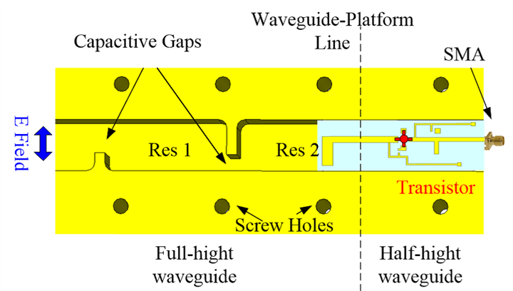
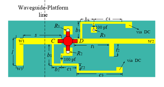 Figure 2 :The 10 GHz filter-amplifier showing (a) the two-resonator waveguide input filter coupled to (b) the microstrip amplifier circuit beam Scanning Metasurface-based Low-Loss Millimetre-wave (60GHz) antenna performance
 Figure 3: photograph of the filter-amplifier
The design is based on filter synthesis principles enabling standard filter functions to be included in the transmission characteristics of the filter-amplifier. The physical structure is waveguide resonators followed by a microstrip based amplifier. This is show in figure 2 with a photograph in figure 3. The key to the design is the resonator which couples to the microstrip probe (resonator 2). This resonator is a combination of the actual waveguide, the probe and part of the input microstrip. The resonator frequency is controlled by the size of these structures as well as the input impedance of the transistor in the amplifier. Correct design provides a compact, efficient filter-amplifier with good performance. Experimental results compared with the simulation are shown in figure 4. The measured S-parameters response displays a two-pole Chebyshev filtering characteristic and also gain.
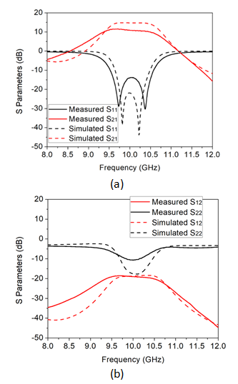 Figure 4: circuit simulation and measurement results. (a) Scattering parameters S11, S21. (b) Scattering parameters S22, S12.