There is considerable work in the group on multipliers and mixers, particularly at terahertz frequencies. Here the design and performance of a WR-5 band Schottky diode based frequency tripler which uses waveguide resonator filters for low loss impedance matching is described. This is an example of work in this area and mixers have also been developed in a similar way. The conventional approach is to design filters and matching networks separately and then to combine them in series to fulfil the design requirement. Here the tripler design is integrated with the input and output filters. The device presented here is a 47.5 to 142.5 GHz bias-less frequency tripler with a 15 GHz output bandwidth.
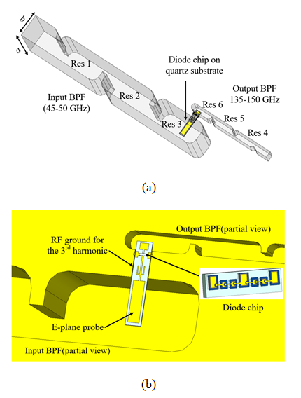 Figure 1: the layout of the tripler with input and output waveguide filters fully integrated (a) The whole structure (b) enlargement of the microstrip tripler area.
Referring to the diagram of the tripler shown in figure 1, the input and output connections to the diodes are coupled to the 3rd and the 6th resonators via two E-plane probes on the suspended microstrip. This results in a mixed type of resonator where one port is waveguide and the other is microstrip. The impedance of the diode is complex and is fully taken into account during the design of the mixed (waveguide and microstrip) resonator.
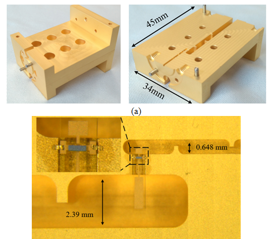 Figure 2: photographs of the fabricated tripler. (a) tripler block. (b) Enlarged view of the microstrip circuit area.
The split-block waveguide part of the tripler is CNC machined from brass stock which is then gold electroplated. The substrate for the suspended microstrip circuit is 50 µm thick fused quartz: the diode chip is fixed to the gold microstrip by soldering. Figure 2 shows three photographs of the components before assembly. These structures we made by our collaborators at the Rutherford Appleton Laboratory, UK.
Measurements of the tripler were performed for input frequencies from 43 to 51 GHz at an input power level of 17 dBm. The measured output power and S11 are shown in Figure 3. Here the maximum pass-band S11 is around -15 dB while the conversion loss over the design band (135-150 GHz) is 13.1 to 14 dB, corresponding to 4 to 5% efficiency. Overall very good agreement between simulation and measurement is achieved, especially for the S11 response, where the three predicted reflection poles are clearly visible in the measured response. This demonstrates the validity the resonator matching method, the design procedure, accurate knowledge of the diode parameters and the precision of manufacture and assembly.
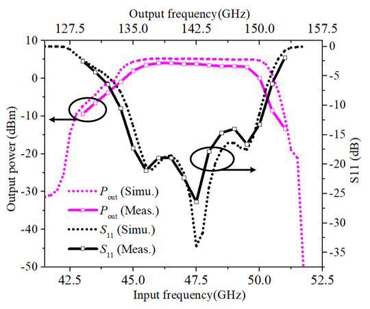 Figure 3: simulated (dashed lines) and measured results (solid lines) for output power and input return loss of the tripler driven by an input power of 17 dBm.
This technique of essentially removing matching networks and replacing them with filters has wide ranging applications and amplifier and mixers are being demonstrated by the EDT group at terahertz frequencies. This project is moving towards an integrated system where the filters are used to connect the components replacing lengths of waveguides.