In addition to the resonators based components described above the EDT group has designed and developed antennas and antenna arrays based on resonators for use in the design of wireless communication and radar systems. The novel aspect is that the resonators are used for filtering as well as radiating. An antenna is a passive device used for transmitting or receiving a microwave signal. An example of the use of conventional antenna array is shown in figure 1 (a). The transmitted microwave signal is sent first to a bandpass filter, where the bandpass filter selects the required frequencies and rejects unwanted frequencies, the signal is then split with the power splitter, there is a set of distribution and matching circuits followed by the radiating elements. Here we exploit the fact that the antenna elements are resonators themselves, enabling us to remove the band pass filter and combine it with the antenna. This is shown in figure 1 (b). The advantages of combining antennas and filters are to reduce the size of the component and also improve the performance of frequency selectivity of the filter. The new component is named an Filter-Antenna.
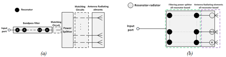 Figure 1: A conventional receiving system and a modified receiving system using an antenna filter.
The design of an antenna array using this technique is described briefly here. The design of the component can be done using conventional filter design; that is the coupling matrix based design method widely used in the EDT group.
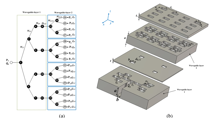 Figure 2: the structure of the 7th order 4×4 filtering planar antenna array (a) resonator coupling topology (b) physical layout
The example given here is a 39 resonator waveguide filter-antenna array with a return loss of 20 dB and a band pass from 9.5 GHz to 10.5 GHz. It is based on the coupling topology in figure 2 (a) and the physical structure is shown in figure 2 (b). The EDT group has fabricated this example and a photograph of the filter-antenna array is shown in figure 3.
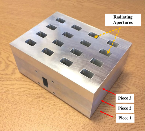 Figure 3: Fabricated filter antenna array
The array has an excellent filtering response for both the return loss (S11) and the normalized gain. The results of the antenna are being shown in figure 27. Realised gain, S11 and radiation patterns are shown.