
Birmingham Tri-Beam System
University of Birmingham was awarded a strategic grant by the Engineering and Physical Sciences Research Council (grant: EP/T-31379/1), to develop a multi-scale, high-resolution, tri-beam facility for fast machining and 3D characterisation.

The project was developed jointly with ThermoFisher Scientific. This facility is composed of a customised Helios-5 Laser Hydra UX microscope fully integrated with an MBRAUN glovebox. This system enables the high resolution, large volume characterisation of advanced materials including air-sensitive materials including battery electrode materials.
The Tri-Bean System layout.
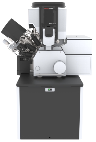
Helios Hydra-Laser Base
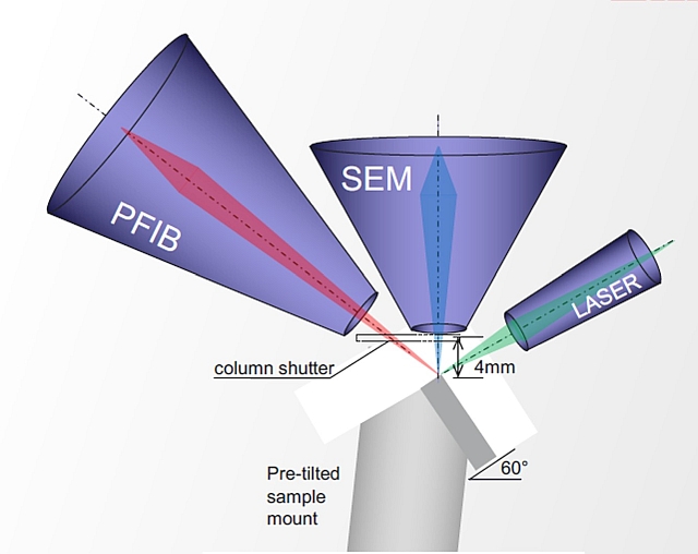
Beam Configuration
We are looking for project collaboration and are now running pilot projects with the aim of demonstrating the uniqueness of our Tri-beam microscope. If you are interested in collaborating with us, please complete the enquiry form.
Case Studies
Case Studies
Discover more about the Centre's expertise through previous case studies, exampled through varied material samples and milling techniques.
Case 1: Femto-second laser milling to excavate materials and to explore features embedded
Example 1: Ceramic material
Dimensions of the milled volume: 1mm x 0.5 mm x 1mm (Depth)
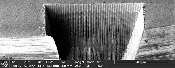
1st step: coarse milling – 4 min
2nd step: fine milling – 10 min
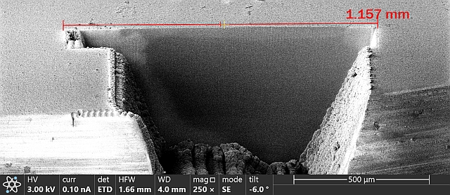
Example 2: Graphite-based electrode material
Dimensions of the milled volume: 1mm x 0.5 mm x 0.5mm (Depth)
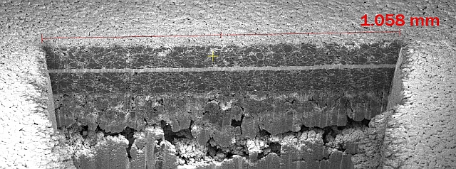
Coarse milling – 1 min; Fine milling – 1 min
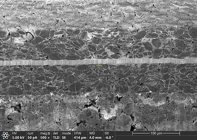
Argon ion fine milling after laser milling
Surface finish after fine laser milling
Followed by further 2 min argon cleaning
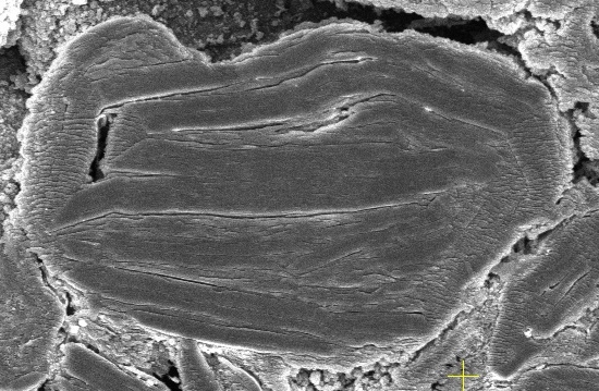
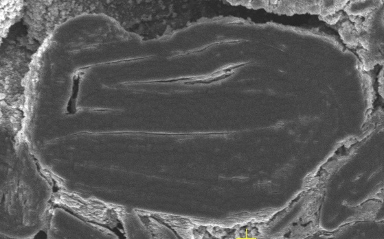
Case 2: Porosity study of electrode material
Objective of this test
To determine the internal structures of the electrode and check the porosity level of the electrode materials.
Method
- Use Argon ion beam and electron beam to perform the slice and view on the electrode samples
- Perform SEM imaging on each slice and 3D reconstruction of the SEM images
Sample Milling Setup
- Sample: Non-graphite based electrode
- Technique: Auto Slice and View
- Argon ion plasma beam
- Slice thickness: 200nm
- Total no. of slices: 200
- Rocking polish: 5°(minimize curtaining effect)
- Total time of slice and view: ~ 20 hours
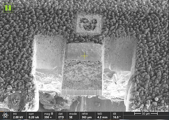
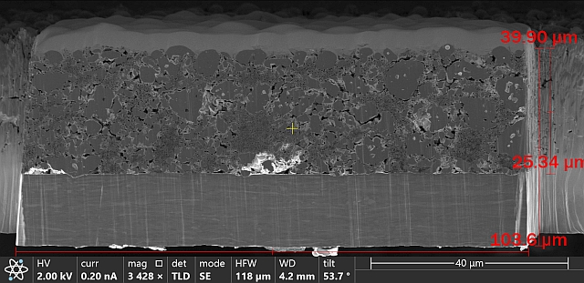
SEM cross-section
3D reconstruction of 200 SEM cross-section images (Avizo)
Slice images at different planes (Avizo)
Observe the change of internal structures
XY plane
YZ plane
ZX plane
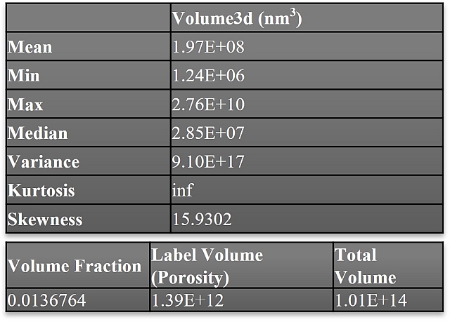
Porosity Analysis using Avizo
Case 3: Large volume EBSD study on 3D-printed steel
Objective of this test
To determine the 3D grain morphology of the steel sample as it evolves and changes across multiple layers.
Method
- Use femto-second laser beam and electron beam to perform the slice and view on the steel rod samples
- Perform EBSD mapping on each slice and 3D reconstruction of the EBSD mappings
Sample milling setup
- Analytical technique: Laser auto slice and view
- Thickness of slice: 10mm
- No. of slices: 122
- Time for Laser milling: 8min per slice
- Time for Ar ion polishing: 2min per slice
- Time for EBSD analysis: 30min per slice (650mmx450mm scanning area)
- Total time of slice and view: 4 days
3D reconstruction of EBSD mappings (IPF X)
2D EBSD mappings (IPF X) at different planes (Avizo)
XY planeYZ plane
XZ plane