A microwave system consists of passive elements such as, filters, matching circuits, power splitter/combiners, diplexers, multiplexers, couplers, antennas and polarisation specific components such as orthomode transducers (OMT) together with nonlinear or active circuits such as mixers and amplifiers. The functionality of the systems requires precise design of both the individual components as well as how they are connected together. A common technique is to make all individual components have terminal impedance of 50 W. Generic example of such a system is shown in figure 1; this is a channelized receiver.
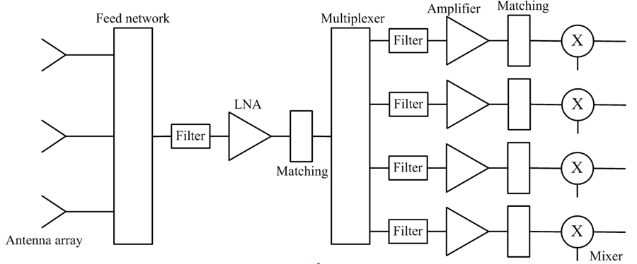 Figure 1: conventional channelizing receiver with antenna array
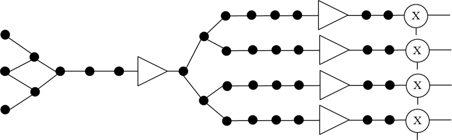 Figure 2: channelizing receiver with resonators. The black dots stand for resonators. Other shapes have the same meanings as the ones shown in Figure 1.
The vision of this work is to replace the conventional concept of individually connected microwave circuits with a concept of a coupled resonator microwave system. It will be discussed below how all the individual passive microwave components mentioned above (i.e. filters, matching circuits, power splitter/combiners, diplexers, multiplexers, couplers and antennas) can be made out of resonators. Figure 2 shows the microwave system of figure 1 as a coupled resonator system; where the resonators are denoted by black dots. It can be seen that the design problem has been changed from the design of individual circuit components to the design of the resonator structure which provides the appropriate functionality of the system.
The advantage of this approach is a much more compact system with improved performance. The reduction in size is enabled in a number of ways, for example (i) the concept of a 50 W impedance is removed, removing all the discrete matching circuits, (ii) filtering can be integrated with other functionality for example the coupling structure or the antenna array (iii) splitting networks, such as manifolds are removed (iv) non-linear or active circuits can easily be integrated with removal of their individual matching circuits. As resonators are used it may be considered that this approach is applicable only to narrow band systems, this is not necessary the case, because, as in filter design, the resonators can be coupled strongly together resulting in an increase in system bandwidth.
It should also be noted this is a two-stage design approach, where the type of resonator (e.g. microstrip, coaxial, waveguide, dielectric etc.) need not be considered until the second stage. The technique can in fact use different types of resonator in one system, choosing the resonator type depends upon the component/system requirements including insertion loss, size, achievable bandwidth, power handling capability and cost. It should be noted that this coupled resonator system demonstrates the ideas, but we are not necessary proposing it should actually be built.