In addition to filters terahertz antennas are an important area for our group. Rectangular waveguide slot antennas have been chosen and are widely used in the field of millimetre-wave applications and radar systems due to having high gain, inherent low transmission losses, and simplicity in fabrication. They also offer significant advantages in terms of weight, volume, and radiation characteristics. These antennas are very attractive due to their planar, compact, and rugged construction and a made by slots in a waveguide. The dimensions and position of the slots in the waveguide walls can be controlled to realise the desired radiation pattern shape.
A micromachined 300 GHz slotted waveguide antenna is demonstrated here using a simple fabrication technique based on metal-coated SU-8 thick resist. The configuration of the design is shown in figure 1. The top layer contains 8 slots which are positioned at the centre of the narrow-wall of the waveguide. The next three layers form the rectangular waveguide, and the whole design is enclosed by the last layer (layer 5).
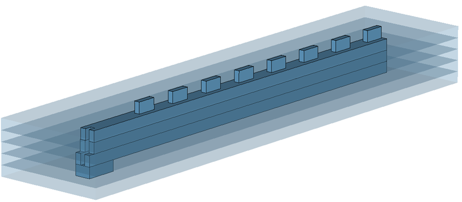 Figure 1: illustration of the design of 8-slots in the narrow-wall of the waveguide with the H-bend input port. The dark blue shows the extent of the air filled waveguide and slot sections,
An embedded five-layer H-plane bend is designed in order to connect the device with the waveguide flange easily and accurately, as shown in Figure 1. The effect of the bend on the performance of the device is negligible. Figure 2 shows the assembled antenna.
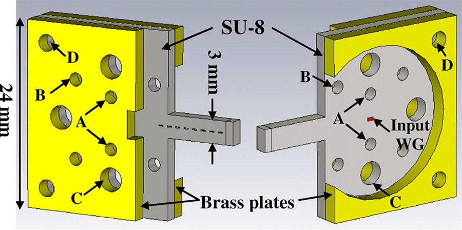 Figure 2: Diagrams of the assembled antenna seen from (left) the radiation side and (right) the feed side. The holes are for (A) precision alignment pins, (B) flange dowel pins, (C) flange screws, and (D) pressure screws.
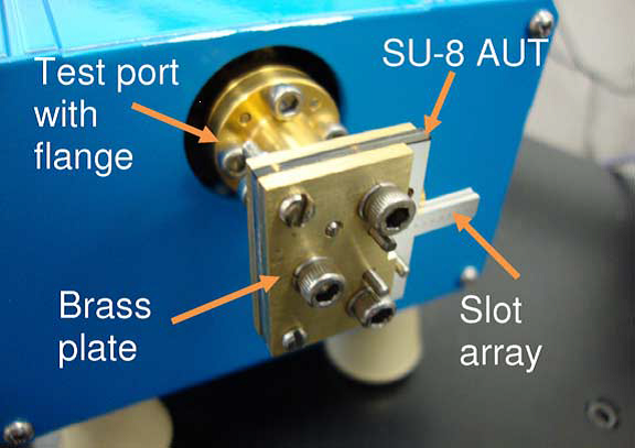 Figure 3: Connection of the 300-GHz slotted waveguide antenna with the test port flange for measurement
The radiation patterns of the antenna were measured at the Rutherford Appleton Laboratory, in an anechoic chamber with a WR-2.8 corrugated feed horn. The mm-wave source module and the detector were connected to a network analyser as shown in Figure 3. At least 40 dB dynamic range was maintained during the measurement. Figure 4 shows the measured normalized H pane radiation pattern which agrees very well with the simulation. This indicates good dimensional accuracy for the radiation slots, rendered by the lithography-based fabrication process.
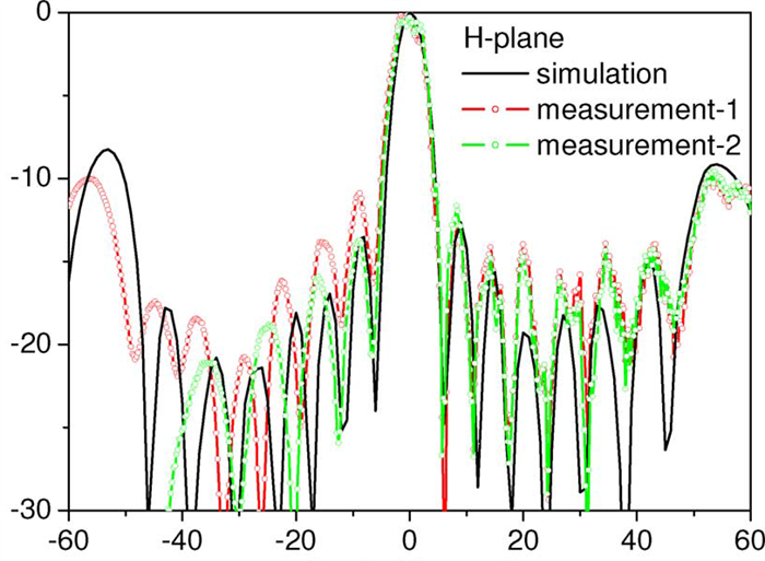 Figure 4: measured H-plane radiation patterns in comparison to simulations. For “measurement-1,” no absorbing material is applied to the antenna. For “measurement- 2,” a sheet absorber is attached to the brass plate on the radiation side. Again, the simulation model includes the brass plates and some metal cylinders representing the effects of the screws.